Author: JD Logistics, Yang Jianmin
The origin of microservices architecture
Monolithic architecture: It can be understood as the main business logic module (the code module we write, excluding independent middleware) running in an application. The most typical example is running in a Tomcat container, located within a single process. The advantages of monolithic architecture are low technical threshold, less programming work, simple and quick development, convenient debugging, easy to set up the environment, easy to release and deploy, and upgrade, with low overall cost of development and operations, and fast results. Its disadvantages are also obvious:
(1) The monolithic application system is rather bloated and cumbersome, with high coupling, making sustainable development and operations difficult.
(2) It is difficult for monolithic applications to bear the rapid growth of user requests and needs.
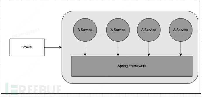
Monolithic application architecture based on Spring Framework
The core idea of distributed architecture is to break a single process system into a group of processes that can collaborate functionally and be independently deployed on multiple servers. In this way, the system can achieve scaling of certain independent components in the following two ways according to actual business needs, thereby improving throughput.
- Horizontal scaling: Expand capacity by increasing the number of servers.
- Vertical scaling: Allocate better machines and more resources to some special businesses in the system to enhance their system load and throughput.
Distributed architecture involves breaking a large monolithic application into multiple independently running processes, which can achieve remote calls in some way. Therefore, the first core technical problem to be solved in distributed architecture is the remote communication between independent processes. The earliest answer to this problem is RPC technology (Remote Procedure Call). The structural illustration of a typical microservices architecture platform is as follows:
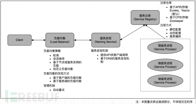
It is well-known that microservices architecture frameworks such as Dubbo and Spring Cloud are popular, and most successful microservices architectures are closely related to container technologies. Among them, the most successful and influential is the Kubernetes platform. Similar to this is Docker Swarm, which was launched by Docker Inc. (By the end of 2017, Docker Swarm also supported Kubernetes).
Due to the limited scope of the article, the advantages of microservice architecture will not be elaborated. However, any technology has its two sides. Microservice architecture has certain complexities, such as developers must master some RPC technology, and they must write code to handle complex issues such as slow RPC speed or call failures. To solve the programming complexity problems brought by microservices, a new architectural design concept has emerged, which is Service Mesh. The definition of Service Mesh is: a complex infrastructure facility for handling service-to-service communication (calls). In essence, Service Mesh is a service network composed of a set of network proxy programs, which are deployed together with user programs to act as service proxies. This proxy was called 'Sidecar' in Google's Istio product architecture, which is actually the idea of using proxy mode to solve the problems of code intrusion and repeated coding. The following diagram shows the simplest architecture of Service Mesh. Service Mesh is not the main character of this session; those who are interested can study it by themselves.

Introduction to k8s
The official original text is: 'K8s is an abbreviation derived by replacing the 8 letters 'ubernete' with 8.
k8s is the full name of Kubernetes, the name originates from Greek, meaning 'helmsman' or 'navigator', and it is the microservice architecture of the first generation of container technology (the second generation is Service Mesh).
Kubernetes originated from Borg within Google, providing an application-oriented container cluster deployment and management system. The goal of Kubernetes is to eliminate the burden of orchestrating physical/virtual computing, network, and storage infrastructure, and to allow application operators and developers to fully focus on self-service operations based on container-centric abstractions. Kubernetes also provides a stable and compatible foundation (platform) for building customized workflows and more advanced automation tasks.
Kubernetes has comprehensive cluster management capabilities, including multi-level security protection and admission mechanisms, multi-tenant application support capabilities, transparent service registration and discovery mechanisms, built-in load balancers, fault detection and self-repair capabilities, service rolling updates and online scaling, scalable resource automatic scheduling mechanisms, and multi-granularity resource quota management capabilities.
Kubernetes also provides comprehensive management tools covering all aspects such as development, deployment testing, and operation and maintenance monitoring.
2.1 Kubernetes Architecture and Components

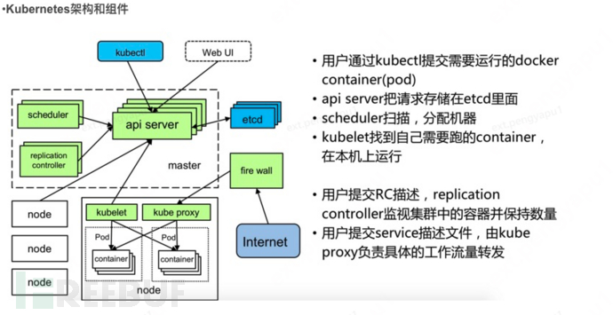
Kubernetes is mainly composed of the following core components:
- etcd stores the entire state of the cluster;
- apiserver provides the only entry point for resource operations, and also provides mechanisms such as authentication, authorization, access control, API registration, and discovery;
- controller manager is responsible for maintaining the cluster's state, such as fault detection, automatic scaling, rolling updates, and so on;
- scheduler is responsible for resource scheduling, dispatching Pods to the corresponding machines according to the predefined scheduling strategy;
- kubelet is responsible for maintaining the lifecycle of containers, as well as managing volumes (CVI) and networks (CNI);
- Container runtime is responsible for image management and the actual running of Pods and containers (CRI);
- kube-proxy is responsible for providing service discovery and load balancing within the cluster for Services;
2.2 Kubernetes Design Philosophy
API Design Principles
API objects are the management operation units in the Kubernetes cluster. Every time the Kubernetes cluster system supports a new feature or introduces a new technology, it will definitely introduce the corresponding API object to support the management operations of that feature. For example, the API object corresponding to the Replica Set is RS.
Kubernetes uses declarative operations, where users define YAML, and Kubernetes' API is responsible for creation. Each object has three major categories of properties: metadata, specification, and status. Metadata is used to identify API objects, and each object has at least three metadata: namespace, name, and uid; in addition, there are various labels used to identify and match different objects, such as users can use the label env to identify different service deployment environments, using env=dev, env=testing, and env=production to identify different services for development, testing, and production. The specification describes the ideal state (Desired State) that the user expects the distributed system in the Kubernetes cluster to reach, for example, the user can set the expected number of Pod replicas to 3 through the Replication Controller; the status describes the actual state (Status) that the system has reached currently, for example, the current actual number of Pod replicas is 2; then the current program logic of the Replication Controller is to automatically start new Pods to strive to reach the number of replicas 3.
apiVersion: apps/v1beta1
kind: Deployment
metadata:
  name: nginx-deployment
spec:
  replicas: 3
  template:
    metadata:
      labels:
        app: nginx
    spec:
      containers:
      - name: nginx
        image: nginx:1.7.9
        ports:
        - containerPort: 80
- apiVersion - Kubernetes API version for creating the object
- kind - What kind of object to create?
- metadata - Data with unique identification of the object, including name (string), UID, and Namespace (optional)
Creating a Deployment using the above .yaml file is achieved by using the kubectl create command in kubectl. Pass the .yaml file as a parameter. For example:
$ kubectl create -f docs/user-guide/nginx-deployment.yaml --record
Common k8s objects: Pod, Replication Controller (Replication Controller, RC), Replica Set (Replica Set, RS), Deployment, Service, Job, Volume, Persistent Volume (PV), Persistent Volume Claim (PVC), Node, ConfigMap, Endpoint, and so on.
Principles of control mechanism design
- Each module can degrade gracefully when necessary, and the control logic of the service should only depend on the current state.To ensure the stability and reliability of distributed systems, for distributed systems that frequently encounter local errors, if the control logic only depends on the current state, it is very easy to restore a temporarily faulty system to normal status, because you only need to reset the system to a stable state, and you can confidently know that all the control logic of the system will start to run normally.
- Assume any possibility of error and implement fault tolerance. Local and temporary errors are likely events in a distributed system.Errors may come from physical system failures, external system failures, or system code errors. Relying on self-implemented code that will not fail to ensure system stability is actually difficult to achieve, therefore, it is necessary to design fault tolerance for any possible error.
- Try to avoid complex state machines, and control logic should not depend on unmonitored internal states.Since the subsystems of a distributed system cannot be strictly synchronized internally through the program, if the control logic of two subsystems has an impact on each other, then the subsystem must be able to access the state that affects the control logic, otherwise, it is equivalent to having uncertain control logic in the system.
- Assume that any operation may be rejected by any operation object, or even misinterpreted.Due to the complexity of distributed systems and the relative independence of different subsystems, which are often developed by different development teams, it is unrealistic to expect that any operation will be processed correctly by another subsystem. It is necessary to ensure that when errors occur, operation-level errors will not affect system stability.
- Each module can recover automatically after an error.Since it is impossible to guarantee that the modules in a distributed system are always connected, each module must have the ability to self-repair to ensure that it will not crash due to the inability to connect to other modules.
- Each module can degrade services gracefully when necessary.Graceful degradation of services refers to the requirement for system robustness, that is, to clearly divide the basic functions and advanced functions in the design and implementation of modules, ensuring that the basic functions do not depend on advanced functions. In this way, it is also ensured that the entire module will not crash due to the failure of advanced functions. Systems implemented according to this concept are also easier to quickly add new advanced functions, as there is no need to worry about the introduction of advanced functions affecting the existing basic functions.
Three. Resource Management
How the container cloud platform manages the available resources for tenants in a fine-grained manner plays a crucial role in the availability, maintainability, and usability of the platform, and is the cornerstone for the platform to provide users with rich microservice management. In the field of cloud computing, resources can be divided into three major categories: computing resources, network resources, and storage resources, which can also be called computing cloud, network cloud, and storage cloud respectively.
3.1 Resource Management
Namespace
In the k8s cluster, the entity that provides computing resources is called Node. A Node can be either a physical server or a virtual machine server, and each Node provides CPU, memory, disk, network, and other resources. Each Node (node) has some necessary services for running pods and is managed by the Master component. The services on the Node include Docker, kubelet, and kube-proxy.
By introducing Namespaces, k8s further divides the cluster into multiple virtual groups for management. The 'partitioning' implemented by Namespaces is logical and does not bind to actual resources. It is used to achieve resource partitioning and maximize resource utilization in multi-tenant scenarios.

Most Kubernetes resources (such as pods, services, replication controllers, or others) are in some Namespace, but the Namespace resource itself is not in a Namespace. Lower-level resources (such as Nodes and persistentVolumes) are not in any Namespace. Events are an exception: they may or may not have a Namespace, depending on the object of Events.
Pod
A Pod is the smallest and simplest basic unit created or deployed by Kubernetes, representing a process running on the cluster.
A Pod encapsulates an application container (it can also have multiple containers), storage resources, an independent network IP, and strategy options for managing the container's runtime. A Pod represents a deployment unit: a single instance of an application in Kubernetes, which may consist of resources shared by a single container or multiple containers.
Each Pod is a single instance running an application. If you need to horizontally scale the application (for example, run multiple instances), you should use multiple Pods, with each instance in a separate Pod. In Kubernetes, this is usually called Replication. The Pods for Replication are usually created and managed by a Controller. A Controller can create and manage multiple Pods, providing replica management, rolling updates, and cluster-level self-healing capabilities. For example, if a Node fails, the Controller can automatically schedule the Pods on that node to other healthy Nodes.
Container
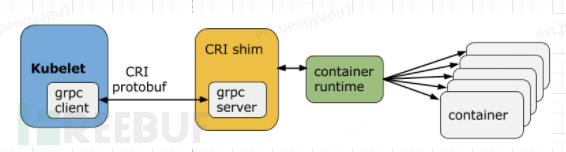
Docker itself is relatively heavy. In 2015, OCI (Open Container Initiative) was born, defining the image standard, runtime standard, and distribution standard. Since Kubernetes itself does not have the ability to create containers, it creates containers by calling the container runtime API interface and commands through the kubelet component. The relationship between Kubernetes and container runtime is historical and also complex. However, with Kubernetes abandoning Docker, the mainstream runtime at present is mainly containerd and CRI-O.
The "one-container-per-Pod" mode is the most common usage of Kubernetes, where a Pod can also contain multiple containers.
Resource management at three levels
In k8s, resource configuration and limitations can be managed at the Namespace, Pod, and Container levels. For example:
- The container level can be configured through the Resource Request and Resource Limits options.
apiVersion: v1
kind: Pod
metadata:
  name: memory-demo-3
spec:
  containers:
  - name: memory-demo-3-ctr
    image: vish/stress
    resources:
      limits:
        memory: "1000Gi"
      requests:
        memory: "1000Gi"
    args:
    - -mem-total
    - 150Mi
    - -mem-alloc-size
    - 10Mi
    - -mem-alloc-sleep
    - 1s
- The Pod level can be set by creating a LimitRange object, which allows for unified configuration of the containers contained within Pods.
apiVersion: v1
kind: LimitRange
metadata:
  name: mylimits
spec:
  limits:
  - max:
      cpu: "4"
      memory: 2Gi
    min:
      cpu: 200m
      memory: 6Mi
    maxLimitRequestRatio:
      cpu: 3
      memory: 2
    type: Pod
  - default:
      cpu: 300m
      memory: 200Mi
    defaultRequest:
      cpu: 200m
      memory: 100Mi
    max:
      cpu: "2"
      memory: 1Gi
    min:
      cpu: 100m
      memory: 3Mi
    maxLimitRequestRatio:
      cpu: 5
      memory: 4
    type: Container
- The Namespace level can provide an overall resource usage limit through the configuration of the ReSourceQuota resource object, which can be either the total amount of computational resources used by all Poids or the maximum total number of objects of a certain type for all Pods (including the number of objects that can be created such as Pods, RC, Service, Secret, ConfigMap, and PVC, etc.).
apiVersion: v1
kind: ResourceQuota
metadata:
  name: pod-demo
spec:
  hard:
  request.cpu: "4"
  request.memory: 8GB
  limit.memory:16GB
  pods: "2"
3.2 Network Resource Management
k8s IP Model
Node Ip: The IP of the node, which is a physical IP.
Pod Ip: The IP of the pod, which is the IP of the docker container, and it is a virtual IP.
Cluster Ip: The IP of the service, which is a virtual IP. Provides a virtual IP within the cluster for pods to access. The implementation principle is through Linux firewall rules, which belongs to NAT technology. When accessing ClusterIP, the request will be forwarded to the backend instances, and if there are multiple backend instances, it will also implement load balancing by default, which is round-robin by default.
Cross-host container network solution
In the k8s system, one of the basic principles in the design of the k8s network model is that each pod has an independent IP address, and it is assumed that all pods are in a flat network space that can be directly connected to each other, regardless of whether they are running on the same Node (host). They can directly access each other through their IP addresses. However, k8s itself does not provide a cross-node container network solution. Public cloud environments (such as AWS, Azure, GCE) usually provide container network solutions, but in a private cloud environment, it still requires container cloud platforms to provide various container network solutions for different tenants.
Currently, setting an Overlay network for containers is the most mainstream cross-host container network solution. An Overlay network refers to encapsulating the original IP packets into a logical network through some additional network protocol without changing the existing network configuration. On the k8s platform, it is recommended to deploy container networks through the CNI plugin method.
CNI (Container Network Interface) is a project under the CNCF Foundation, consisting of specifications and libraries for configuring container network interfaces. It defines the interface specifications between the container runtime environment and network plugins, focusing only on network configuration during container creation and the release of network resources when containers are destroyed. Additionally, a container can bind multiple CNI network plugins to join the network, as shown in the following figure.
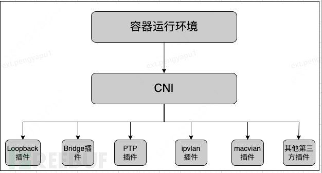
The more common CNI plugin implementation methods currently include Flannel, Calico, macvlan, Open vSwitch, and direct routing.
Ingress
Within the k8s cluster, applications are provided by default in the form of Services, with kube-proxy implementing the function of the load balancer from Service to containers, as shown in the following figure: Define a mysql service:
kind: Service
apiVersion: v1
metadata:
  name: mysql-master
spec:
  selector:
    app: mysql-master
  ports:
      port: 3306
      targetPort: 3306
At this time, it is not possible to access this Service from outside the cluster. For Services that need to provide services to clients outside the k8s cluster, Ingress can be used to expose the service, and if the cluster (network) has a real domain name, the Service can also be directly connected to the domain name.
K8s combines the definition of an Ingress resource object with a specific Ingress Controller to implement a 7-layer load balancer. When the Ingress Controller forwards client requests to the backend service, it will bypass the 4-layer load balancer function provided by kube-proxy and directly forward to the backend Pod (Endpoints) of the Service to improve network forwarding efficiency.
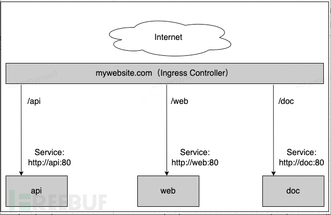
As shown in the figure above, this is an example of a typical HTTP layer routing Ingress, where:
- Access to http://mywebsite.com/api will be routed to the backend Service named 'api';
- Access to http://mywebsite.com/web will be routed to the backend Service named 'web';
- Access to http://mywebsite.com/doc will be routed to the backend Service named 'doc'.
The following is an example of a typical Ingress policy definition. The Ingress Controller will forward access requests to the target address http://mywebsite.com/demo to the internal service webapp (webapp:8080/demo) in the cluster.
apiVersion: extensions/v1beta1
kind: Ingress
metadata:
   name: mywebsite-ingress
spec:
   rules:
   -host: mywebsite.com
    http:
       paths:
      - path: /demo
          backend:
           serviceName: webapp
           servicePort: 8080
Commonly used Ingress Controllers include: Nginx, HAProxy, Traefik, and apisix, etc.
3.3 Storage resources
Volume types supported by k8s
Temporary directory (emptyDir)
When using emptyDir, an emptyDir will be created when the Pod is allocated to a Node, and the Volume will remain as long as the Pod keeps running on the Node. When the Pod (for any reason) is deleted from the Node, the emptyDir will also be deleted, and the stored data will be permanently deleted. Note: Deleting the container does not affect the emptyDir.
Configuration class
- ConfigMap: Mounts configuration file information stored in the ConfigMap resource object to a directory within the container
- Secret: Mounts password keys and other information stored in the Secret resource object to a file within the container
- DownwardAPI: Injects downward API data into the container as environment variables or files
- gitRepo: Mounts a Git code repository to a directory within the container
Local storage class
- hostPath: Mounts the host's directory or file into the container for use
- local: Introduced in version v1.9, provides local storage to containers in the form of PV and can manage storage space
Shared storage class
- PV (Persistent Volume): Defines shared storage as a "persistent storage volume" that can be shared by multiple containers
- PVC (Persistent Volume Claim): A user's request for storage resources, the object of which is PVC. Once the application is successful, the shared storage volume can be used as if it were a local directory. The following figure is a PV object definition in YAML format:
apiVersion: v1
kind: PersistentVolume
metadata:
  name: example-pv
  annotations:
        "volume.alpha.kubernetes.io/node-affinity": '{
            "requiredDuringSchedulingIgnoredDuringExecution": {
                "nodeSelectorTerms": [
                    {"matchExpressions": [
                        {"key": "kubernetes.io/hostname",
                          "operator": "In",
                          "values": ["example-node"]
                        }
                    ]}
                 ]}
              "}
spec:
    capacity:
      storage: 100Gi
    accessModes:
    - ReadWriteOnce
    persistentVolumeReclaimPolicy: Delete
    storageClassName: local-storage
    local:
      path: /mnt/disks/ssd1
PV and PVC
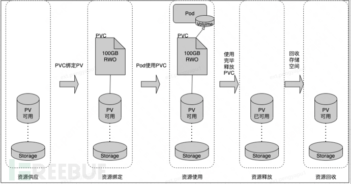
The lifecycle relationship between PV and PVC is shown in the figure above. The shared storage supply mode of k8s includes static mode (Static) and dynamic mode (Dynamic), and the result of resource supply is the created PV. The manual creation of PV by the operation and maintenance personnel is static, and the key to the dynamic mode is StorageClass, which serves to create PV templates.
When creating a StorageClass, it is necessary to define PV attributes such as storage type and size; in addition, a storage plugin is required to create this type of PV. The final effect is that when the user submits a PVC, specifying the storage type, if it conforms to the StorageClass we define, it will automatically create a PV and bind it.
The following figure creates a StorageClass object through yaml
kind: StorageClass
apiVersion: storage.k8s.io/v1
metadata:
  name: standard
provisioner: kubernetes.io/aws-ebs    // Storage allocator
parameters:
  type: gp2
reclaimPolicy: Retain   // Recovery policy
mountOptions:
  - debug
The operation relationship between StorageClass and PV, PVC is shown in the following figure:

CSI
The relationship between CSI (Container Storage Interface) and k8s is somewhat similar to CNI. CSI aims to establish a set of standard storage access interfaces between containers and shared storage. Before its birth, it went through the 'in-tree' method and FlexVolume mode.
The terminology of the CSI specification completely decouples the storage provider code from the k8s code, and the code of the storage plugin is maintained by the storage provider itself.
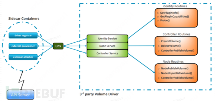
The sidecar containers provided directly by the K8S official for direct interaction with kube-apiserver can be deployed directly. These sidecar containers (mainly the three main components shown in the upper figure) listen to their corresponding CRD, trigger the corresponding operations, and directly call the interfaces of the CSI driver (such as CreateVolume(), NodePublishVolme(), etc.) through the UDS interface to implement operations on the volume.
To develop CSI Drivers, generally implement the following services:
- CSI Identity service
It allows the caller (Kubernetes components and CSI sidecar containers) to identify the driver and the optional features it supports.
- CSI Node service
NodePublishVolume, NodeUnpublishVolume, and NodeGetCapabilities are required.
The required methods enable the caller to make the volume available at the specified path and discover which optional features the driver supports.
- CSI Controller Service
Implement the CreateVolume and DeleteVolume interfaces
3.4 Multi-cluster Resource Management Solution - Cluster Federation (Federation)
Federation is a subproject of Kubernetes, with the design goal of managing multiple Kubernetes clusters uniformly and deploying user applications to data centers in different regions. Federation introduces a control plane located on the Kubernetes cluster, which shields the backend k8s subclusters and provides a unified management entry for customers, as shown in the following figure:
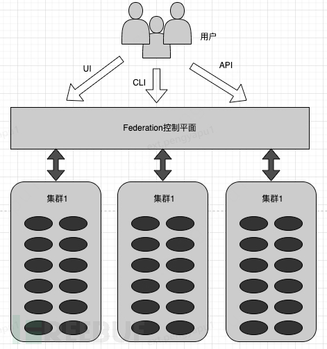
The Federation control plane 'encapsulates' the Master role of multiple k8s clusters, providing a unified Master, including Federation API Server, Federation Controller Manager. Users can operate Federation as if they were operating a single cluster, and it also unifies the DNS, ConfigMap of all k8s clusters, and stores data in the centralized etcd database.
For readers
For beginners in k8s, their first impression of k8s should be that there are many concepts and many terms. The book 'Kubernetes: The Definitive Guide: Enterprise-Class Container Cloud Practice' starts from the perspective of enterprise practice, tells the evolution of technology, and provides comparisons of different technical implementations in many scenarios. Combined with the k8s Chinese community, this book can be used as an introductory book for learning k8s. This article is actually a reading note of this book, which unfolds from the three directions of computing resources, network resources, and storage resources, and introduces some common concepts and objects in k8s. Due to the length of the article, many important concepts are not described in detail, and readers can supplement their learning according to their own situation. The core components and working principles of k8s will be introduced in subsequent articles.

评论已关闭