In the previous article, we learned the basic concepts of the Internet of Things and introduced the hardware and firmware knowledge of IoT devices, taking the IoT terminal as the entry point. In the following, the author will introduce the firmware acquisition methods, file system extraction, and analysis skills of IoT terminal devices.
01 Firmware Acquisition
To analyze the firmware content, it is necessary to obtain the firmware image file first. The following methods can be used to acquire the firmware:
- Obtain the firmware through the official upgrade package provided;
- Consult after-sales support to obtain the upgrade firmware;
- Use a programmer to read Flash, hard disk, and obtain the firmware;
- Obtain the firmware using debugging interfaces such as uart;
- Obtain the firmware through ports such as telnet, ssh, etc.;
- Capture the device's update requests to obtain the firmware download address;
- Obtain arbitrary command execution permissions for the device through known vulnerabilities to acquire the firmware.
1.1 Firmware Acquisition from the Official Website
Some manufacturers provide firmware downloads in their official website after-sales support area to allow consumers to manually upload firmware updates to their devices.
- D-Link http://support.dlink.com.cn:9000
- TP-Link https://service.tp-link.com.cn/download?classtip=software&p=1&o=0
- MERCURY https://service.mercurycom.com.cn/download-list.html
- Tenda https://www.tenda.com.cn/download/cata-11.html
- Ruijie http://www.ruijie.com.cn/fw/rj/
- ASUS https://www.asus.com.cn/support/Download-Center/
- NETGEAR http://support.netgear.cn/download.asp
- Cisco https://www.cisco.com/c/zh_cn/support/all-products.html
- Xiaomi http://www.miwifi.com/miwifi_download.html
1.2 Obtain firmware with programmer
When it is impossible to obtain the firmware through the official website or after-sales service, you can obtain the firmware by reading the device Flash or hard disk through the programmer. Before extracting the firmware, the following extraction tools need to be prepared:
- Screwdriver set:Dismantle the outer packaging of the Internet of Things terminal device
- Two-in-one desoldering station:Desolder Flash, hard disk, etc.
- Chip holder:No need to disassemble Flash, hard disk, read firmware
- Programmer:Can read and write data on programmable integrated circuits, common programmer models include CH341A, RT809F, etc.
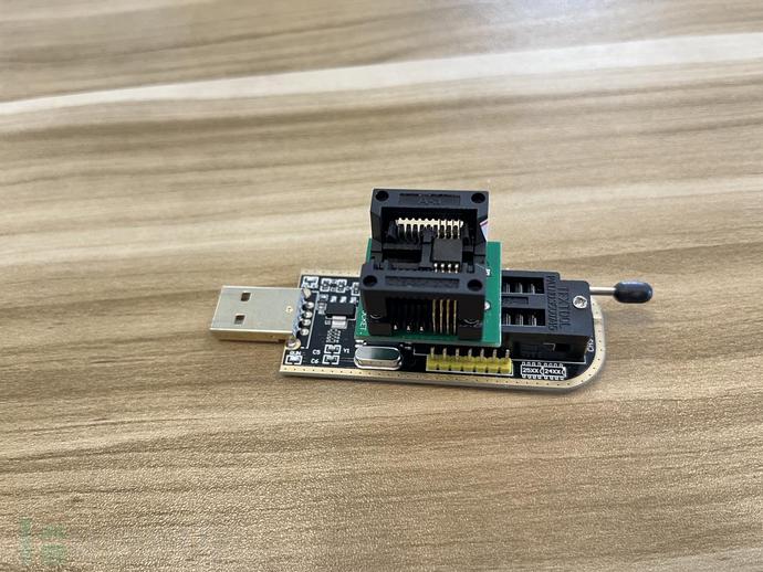
- Socket:Used for placing chips
- Install software:CH341A driver, CH341A burning tool, SSCOM, PUTTY
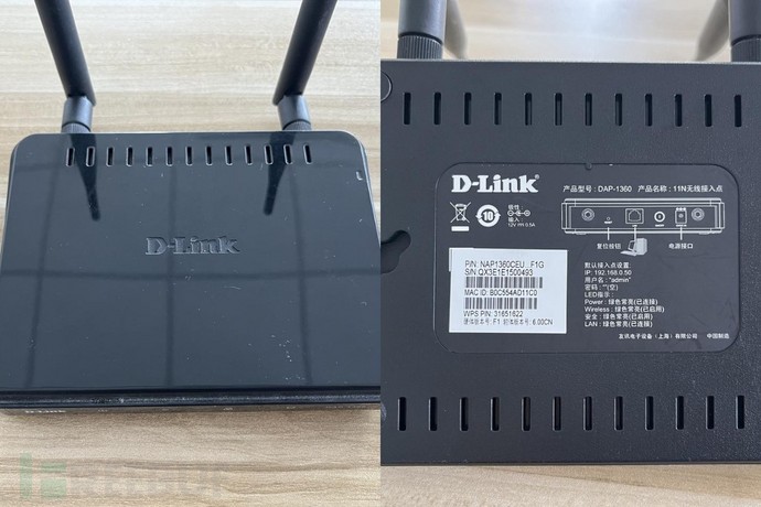
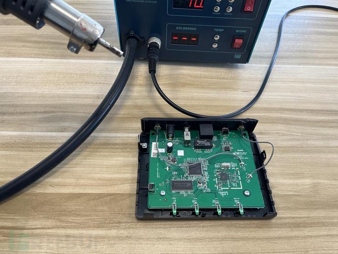
Taking the D-Link DAP1360 modem as an example, we explain the typical steps for the programmer to obtain the firmware:
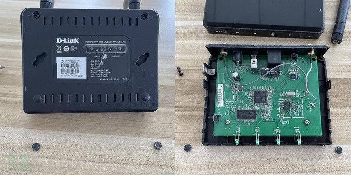
1. Dismantle the outer packaging of the Internet of Things terminal device
When dismantling the Internet of Things device, the first thing to do is to find the position of the screws placed in the outer packaging. It should be noted that some screw positions may be hidden by foot pads, label instructions, and need to be carefully searched to avoid violent disassembly.
After complete disassembly, the PCBA board diagram of DAP1360 is as follows.
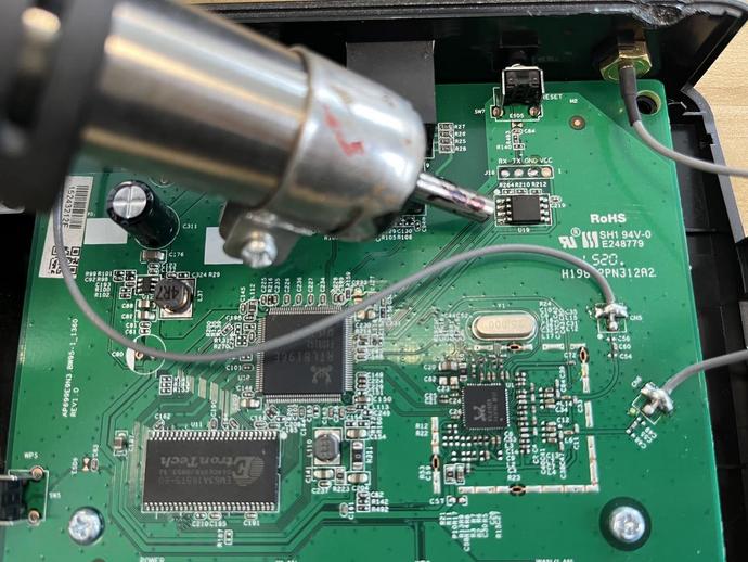
2. Find the storage chip
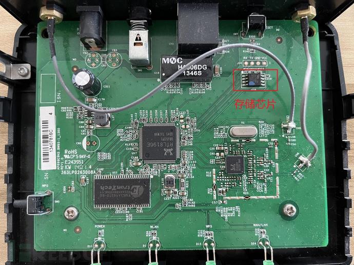
Since the circuit architecture of this Internet of Things terminal device is relatively simple, the eight-pin chip in the upper right corner can be clearly seen as the storage chip of the device. It is also mentioned in the "Understanding Internet of Things Terminal" chapter that the firmware of Internet of Things terminal devices is usually stored in external storage chips.
Note:When there are many chips on the circuit, and it is impossible to confirm the storage chip, you can useComponent search websiteSearch for the chip model.
3. Install programmer driver + programmer burning tool
Before using the programmer, you need to install the corresponding driver. Here, we use the programmer chip CH341A, so install the driver for CH341A.
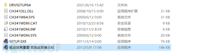
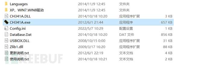
The programmer burning tool does not need to be installed and can be used directly.
4. Confirm the chip model
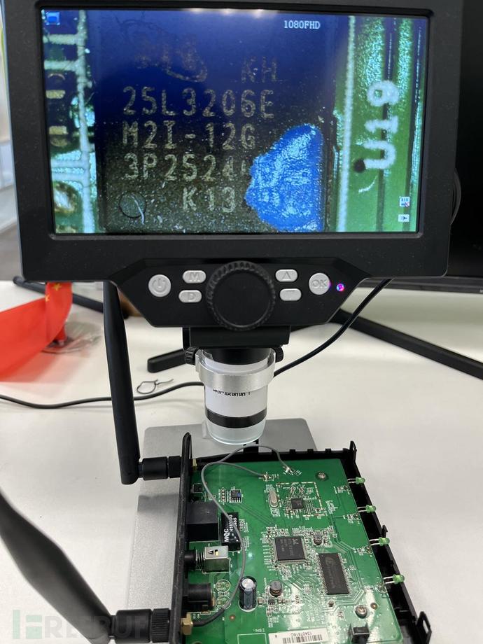
Before dismantling the chip, you need to confirm the model number of the storage chip. Since some storage chip specifications are small, the model number on the chip cannot be seen with the naked eye, and a microscope is needed to view it. As shown in the figure below, the storage chip model of DAP1360 is 25L3206E.
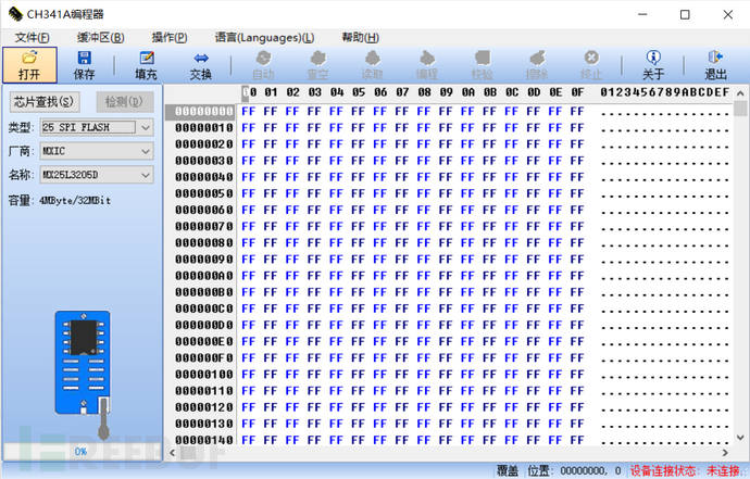
After confirming the model number of the storage chip, insert the programmer into the USB port of the computer and open the burning tool. At this time, if the programmer driver is installed correctly, the device connection status in the lower right corner of the burning tool will display connected, otherwise it indicates that there is a problem with the previous steps, and you need to go back and check one by one.
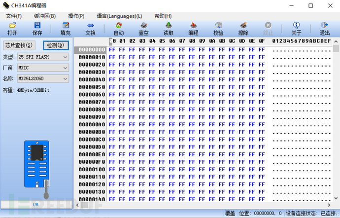
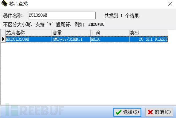
Click the chip search button in the upper left corner, input the model number of the storage chip, and select the corresponding model. It should be noted that the protocol type of this storage chip is "25 SPI FLASH".
5. Chip holder identification
Using the chip holder can avoid removing the storage chip of the IoT terminal device, which is usually used in situations where the device is expensive or it is麻烦 to remove the storage chip. When using the chip holder to obtain the firmware, the power supply of the storage chip is provided by the PC end, and there is no need to connect the device power supply.
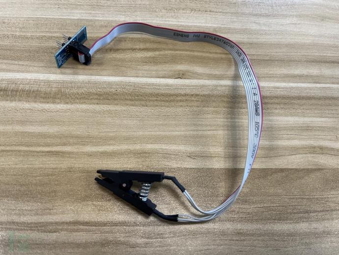
Align the eight pins of the chip holder with the eight pins of the storage chip and clamp it on the storage chip. Since the power supply of the device is provided by the PC end, when the chip holder is connected to the storage chip correctly, the corresponding power light and other indicator lights will usually be on. If the power light and other indicator lights flash or are on and off at will, it indicates that the chip holder is not properly held.
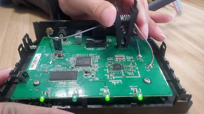
When the indicator light of the device is always on and stable, click the detection button at the upper left corner of the burning tool to correctly identify the information of the storage chip.

When using the chip holder for the first time, multiple attempts are needed to identify it successfully, and during the process of reading the firmware, if the chip holder is not held firmly, the firmware reading will be interrupted, lacking stability, which is also the defect of the chip holder.
Precautions: When using the chip holder, the device cannot be powered on, otherwise there is a possibility of burning the device or programmer.
6. Remove the storage chip
We start the two-in-one soldering station, wait for the hot air machine to heat up until the preset temperature of 250℃.
We aim the hot air machine at the solder joints of the storage chip on both sides, and use tweezers to hold the storage chip until the solder on both sides melts and can be easily removed with tweezers.
Precautions:The hot air machine has a high temperature, prevent burns; there are many small components on the circuit board, pay attention not to blow off the small components when heating the solder of the storage chip.
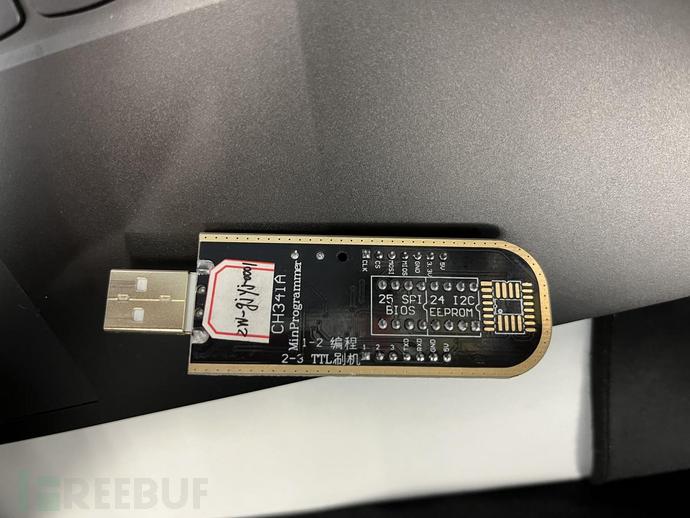
Then we put the storage chip into the socket and connect it to the programmer. The CH341A programmer supports 25SPI and 24IIC protocols, and our storage chip is 25SPI protocol, so we insert the socket into the 25SPI area of the programmer.
7. Extract firmware
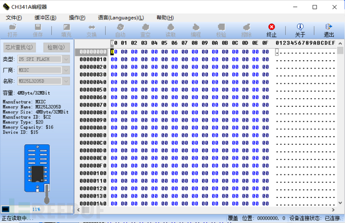
Open the burning tool, click the detection button at the upper left corner, and you can see that the burning tool can read the relevant information of the storage chip. If the burning tool fails to correctly read the values of the four parameters below, the hexadecimal numbers are displayed as $FF or $00, it may be that the chip model selected at the chip search location does not match or the programmer's socket is inserted in the wrong direction.

(Identification successful image)
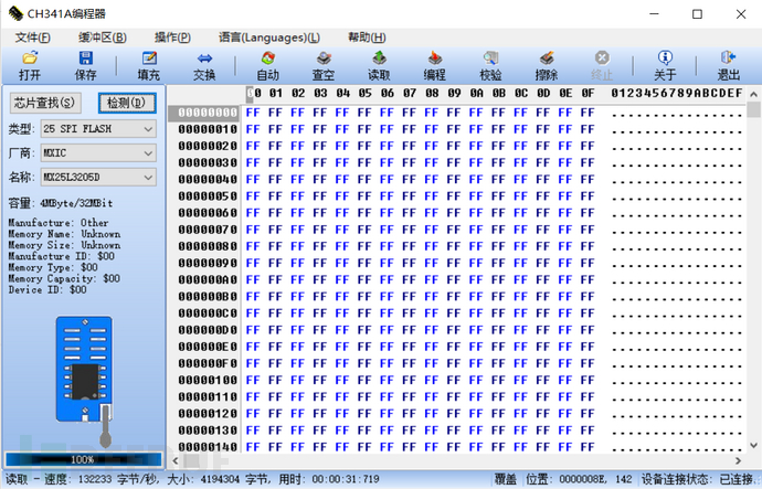 (Identification failed image)
After the storage chip is successfully identified, we click the read button at the top, and the progress bar at the lower left will gradually increase, indicating that it is reading. After the firmware is read, click the save button at the top, select the directory, and name the saved file as xxx.bin to obtain the firmware of the device.
1.3 Shell firmware acquisition
When it is impossible to obtain the firmware of an IoT device through the official website or programmer, we usually use the terminal device shell to obtain the firmware. Common methods to obtain the device shell are:
- uart debugging interface
- telnet, ssh service port
- Known any command execution vulnerability
Among the methods mentioned above to obtain shell, the method of uart debugging interface has a more complex and comprehensive operational process. We will take the method of obtaining shell through uart debugging interface as the main content of this section.
The book "Understand the Internet of Things Terminal" explains the theoretical knowledge of uart. Now we will learn the usage method of uart debugging interface through actual cases. Before using the uart debugging interface, some debugging tools need to be prepared:
- TTL to USB module
- Set of Dupont wire
- Multimeter
1. Install serial port debugging tools
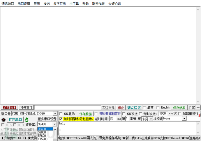
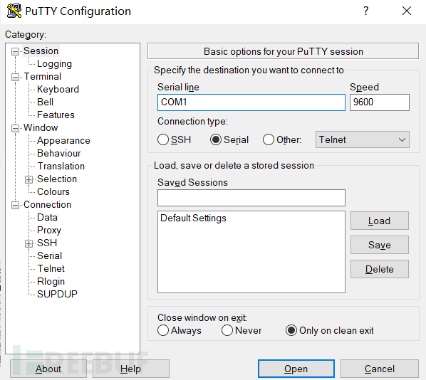
There are two serial port debugging tools installed here. The first one is SSCOM, which can automatically identify the TTL to USB module and provide common baud rate options, which is convenient for testing baud rate. The second one is PUTTY, which supports command line interaction and makes the debugging process more convenient.
It should be noted that only one of the two tools can be used at a time, otherwise a COM occupied warning will be displayed.
2. Connect uart serial port
According to the content of this chapter of "Understand the Internet of Things Terminal", we know that uart serial ports are usually composed of 4 pins (Rx, Tx, Vcc, GND), and next we will find the corresponding pins on the uart serial port with the multimeter.
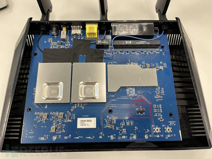
We use NETGEAR R7000 as a demonstration case. You can clearly see that there are 4 soldered pins on the PCBA board, which are officially used for debugging the uart serial port. We sort the 4 pins from left to right as 1-4.
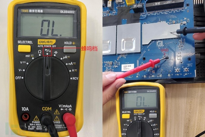
Connect the terminal device to the power supply, take out the multimeter, and adjust it to the buzzer range (there will be a buzzing sound when the red probe and black probe touch). Place the black probe against the metal heat sink (ground open circuit), and touch the red probe in turn between the 1st to 4th rows of pins. It is found that the 2nd row of pins emits a buzzing sound, so it can be determined that the 2nd row of pins is the GND pin.
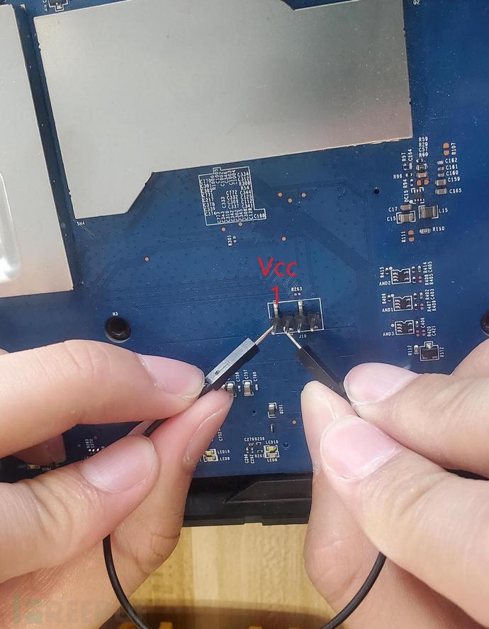
Then use the Dupont wire to short-circuit the remaining 3 rows of pins with the 2nd row of pins in turn. If the terminal device restarts, it indicates that the pin short-circuited with the 2nd row of pins is the Vcc pin. During the test, it is found that the 1st row of pins is the Vcc pin.
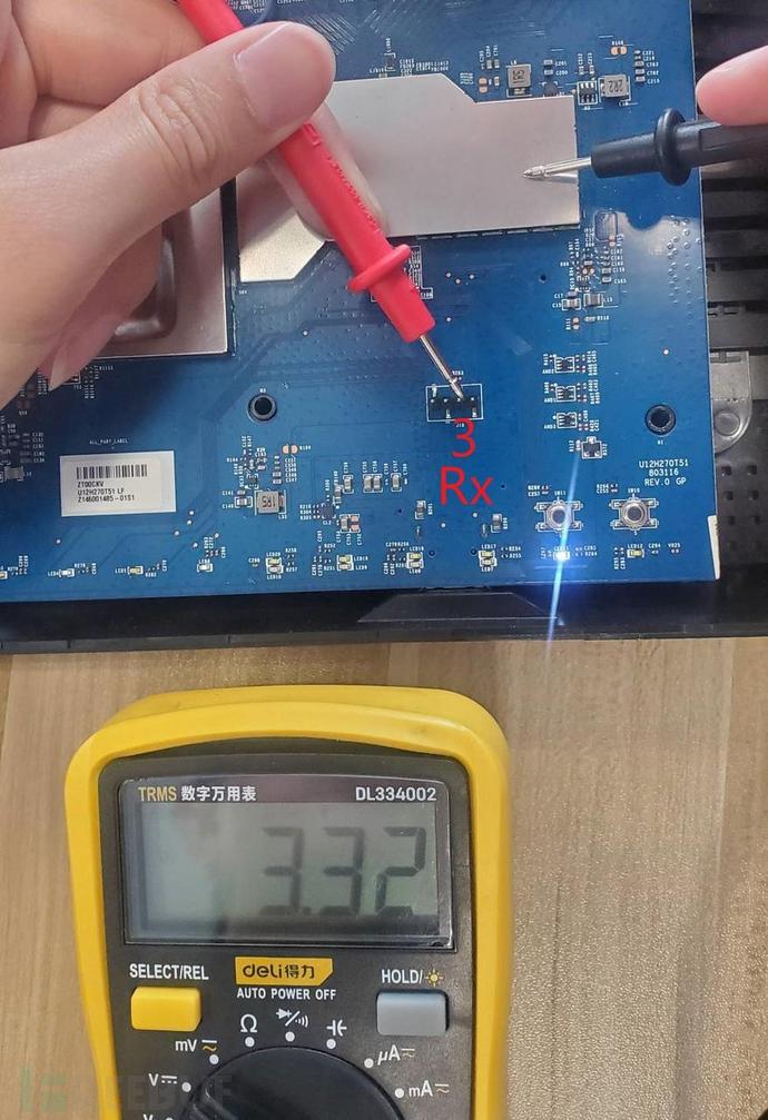
Adjust the multimeter to the DC voltage range, connect the black probe to the GND pin, and measure the voltage of the 3rd and 4th rows of pins. It is found that they are about 3.3V. Since the terminal device will perform data transmission when it starts up, the voltage of the Tx pin will change frequently. At this time, you can observe the voltage change of the two rows of pins by restarting the device. Through testing, it is judged that the 3rd row of pins is the Tx pin, and the 4th row of pins is the Rx pin.
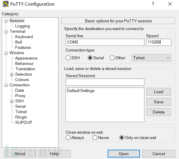
According to the introduction of uart pin and TTL to USB module connection method in the article "Understand the Internet of Things Terminal", connect the device uart serial port on the PC side. By continuously debugging the baud rate, we finally determine that the baud rate of the uart serial port of this terminal device is 115200.
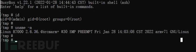
After confirming the COM port and baud rate of the uart serial port with SSCOM, we press the "Open" button in PUTTY. After receiving the initialization information of the device, we input the command "id" to confirm that the current permission is root; input the command "uname -a" to see the relevant information of the device.
3. Extract firmware
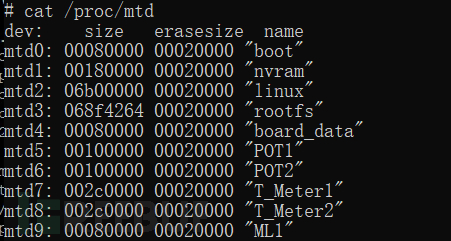
The storage chip of the terminal device is usually mounted on the file system. We can see the starting address and byte size of the mounted boot, kernel, and file system by executing the command "cat /proc/mtd", among which the location of the mounted file system "rootfs" is mtd3.
The proc/mtd file in the figure saves the system disk partition information. The "boot" partition of mtd0 saves the system boot-up program; the "nvram" partition of mtd1 saves various configuration data of the system settings, such as administrator account passwords, etc.; the "linux" partition of mtd2 saves the Linux kernel program; the rootfs partition of mtd3 saves the data of the file system. Other partitions are used according to the developer's design.
Use the dd command to obtain the device file system image: "dd if=/dev/mtd3 of=/tmp/R7000.bin"
After obtaining the file system image, how to use the command to transmit the firmware externally is a question. The author has compiled the following several commonly used firmware transmission methods:
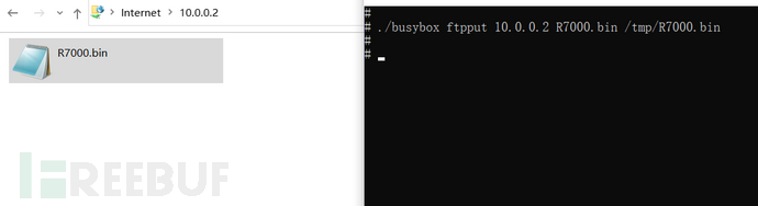
- ftp command
If the shell supports the ftpput command, first you need to set up aftp server, use the command "ftpput 10.0.0.2 R7000.bin /tmp/R7000.bin" to upload the firmware to the local ftp server. In the test case, the local IP is 10.0.0.2, and the IoT terminal IP is 10.0.0.1.
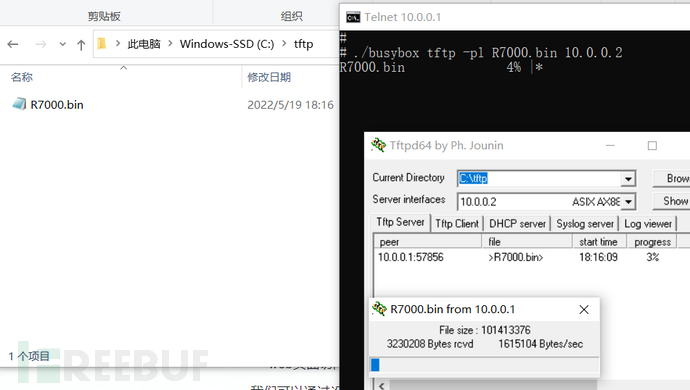
- tftp command
If the shell supports the tftp command, first download it on the local machinetftp tool, enable the tftp server. Under the /tmp directory of the file system of the terminal device, use the command "tftp -pl R7000.bin 10.0.0.2" to upload the firmware to the tftp server on the local machine. In the test case, the local IP is 10.0.0.2, and the IoT terminal IP is 10.0.0.1.
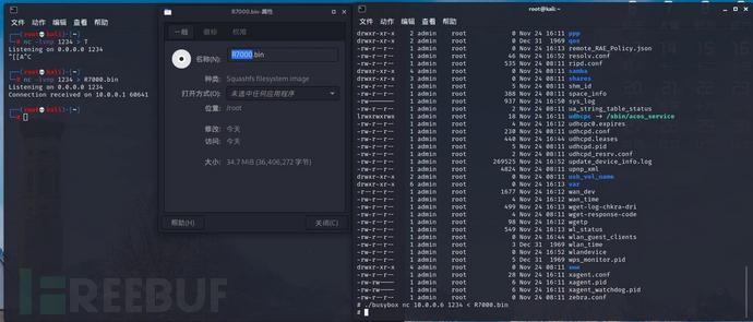
- nc command
If the shell supports the nc command, first execute the command "nc -lp 1234 >R7000.bin" on the local terminal shell, and then execute the command "nc 10.0.0.6 1234 <R7000.bin" on the IoT device shell terminal. In the test case, the local IP is 10.0.0.6, and the IoT terminal IP is 10.0.0.1.
- web page acquisition
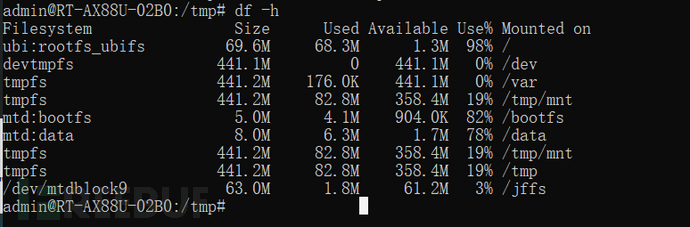
If the shell supports mount and df commands, first use the command "df -h" to check the mount name of the root directory as "ubi:rootfs_ubifs".
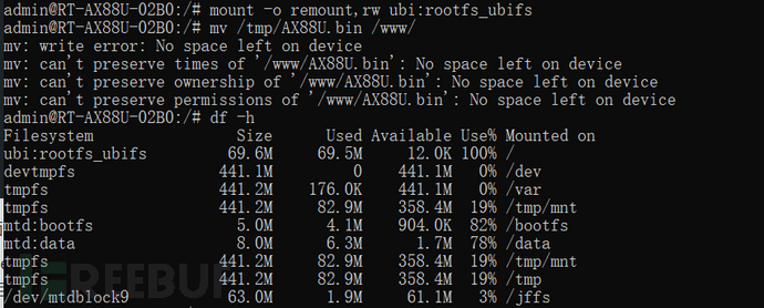
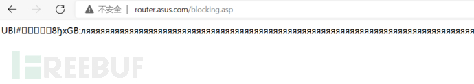
The common /www directory is generally read-only, and the command "mount -o remount,rw ubi:rootfs_ubifs" needs to be used to reset the read and write permissions of the file system. Then, the AX88U.bin file under the /tmp directory is overlaid on the front-end page that can be directly accessed under the /www directory. Due to insufficient memory capacity of the file system, a space shortage prompt is displayed.
The pages covered by the test terminal are /blocking.asp. By accessing the device's front-end page, the firmware is finally downloaded to the local machine.
02 File system
In the second part of 'Understanding Internet of Things Terminal', we introduced the components of the firmware, one of the most important parts of which is the file system. Therefore, in this section, we introduce the commonly used methods for file system extraction.
2.1 File system extraction
The commonly used kernels of Internet of Things terminal devices are mainly Linux and Vxworks. The next section mainly introduces the file system extraction methods of these two systems.
Manual extraction of Linux file system
Before introducing the extraction methods, let us first introduce the system commands commonly used for binary program analysis in the Linux system:
system commands | Function | options |
file | Used for file type identification | -L: view link files |
grep | Used to find strings that meet the conditions in the file | -i: ignore case -s: do not display error information -a: do not ignore binary data |
hexdump | Convert binary files to ASCII, octal, decimal, and hexadecimal formats for viewing | -C: output standard hexadecimal and ASCII codes -n length: format the output of the first length bytes of the file -s: start output from the offset |
strings | Search for printable strings in object files or binary files | -n: display the minimum number of characters -a: scan the entire file |
dd | Read data from standard input or file, convert data according to the specified format, and then output to a file, device, or standard output | if=file name: specify input file of=file name: specify output file bs=bytes: set input/output block size to bytes bytes skip=blocks: skip blocks from the beginning of the input file before starting to copy |
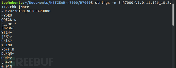
We will take NETGEAR R7000'sV1.0.11.126Version firmware is used as the demonstration case in this section. First, use the strings command to view the strings contained in the firmware.
In the second part of 'Understanding Internet of Things Firmware', we introduced common file systems of Internet of Things terminal devices such as SquashFS, JFFS2, and YAFFS2. These file systems usually have a header string feature in the image:
- SquashFS
The standard firmware big-endian mode is sqsh, the standard firmware little-endian mode is hsqs, the big-endian mode under LZMA compression is sqlz, the big-endian mode of Squashfs file system in version 3.3 under LZMA compression is qshs, some non-standard firmware little-endian mode is shsq, the little-endian mode of DD-WRT firmware is hsqt, and the big-endian mode of DD-WRT firmware is tqsh[1].
- JFFS2
JFFS2 file system usually uses "0x1985" as the header feature identifier.
- Cramfs
The header feature character of Cramfs file system is "0x28cd3d45"
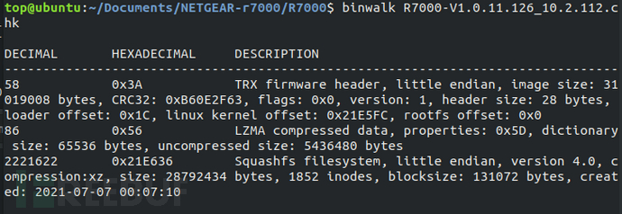
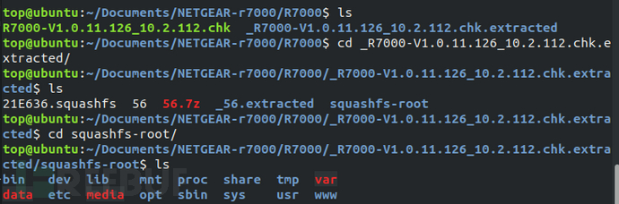
Use the hexdump command to search for the header feature identifier of the above file system, first test the most commonly used SquashFS file system on the terminal device. Use the command "hexdump -C R7000-V1.0.11.126_10.2.112.chk |grep "hsqs"".
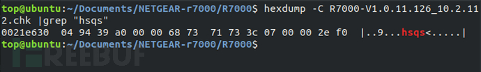
According to the search results, it can be determined that the test firmware is a little-endian SquashFS file system, and the starting address of the file system is 0x21E636.
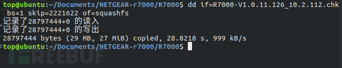
Use the dd command to extract the SquashFS file system image from the test firmware, the complete command is "dd if=R7000-V1.0.11.126_10.2.112.chk bs=1 skip=2221622 of=squashfs". The 'if' specifies the input file, 'of' specifies the output file, 'bs=1' indicates that the unit size of input/output data blocks is 1 byte, and 'skip=2221622' means skipping 2221622 bytes (hexadecimal 0x21E636), which can also be understood as specifying the starting address of the extraction.
Next, use the file command to check the file type of the extracted file system. As can be seen from the figure below, the basic information of some file systems can be identified.
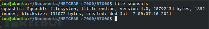
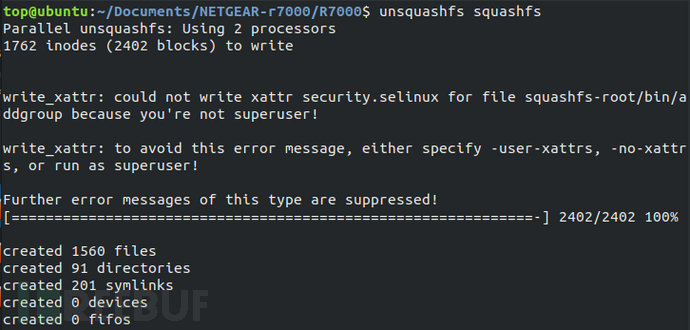
Since SquashFS file system is a read-only compressed file system, it is necessary to useunsquashfsand other open-source tools to extract data.
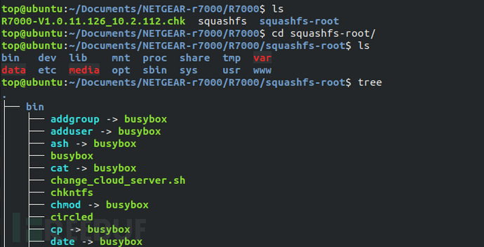
The file structure of the extracted file system image is basically consistent with that of the PC Linux file system.
Automatic extraction of Linux file system
The binwalk toolset integrates various magic signatures of files contained in firmware images such as bootloaders, Linux kernels, and file systems, which can automatically identify these file images and extract their information and data. In addition to the file extraction function, binwalk also supports many functions such as system architecture identification "-A", calculating file entropy "-E", and more. For more details, please refer to https://github.com/ReFirmLabs/binwalk.
We used binwalk to parse the test firmware. As shown in the figure below, binwalk parses out the size endianness, kernel architecture, filesystem type, and other information of the test firmware.
Using the command "binwalk -Me R7000-V1.0.11.126_10.2.112.chk" to recursively scan the firmware image and automatically extract identifiable files. The filesystem extracted by binwalk is consistent with the manually extracted filesystem content.
In addition to the binwalk tool, for ubifs filesystem images, we can also useubi_readertools to extract its filesystem.
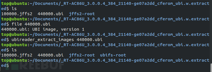
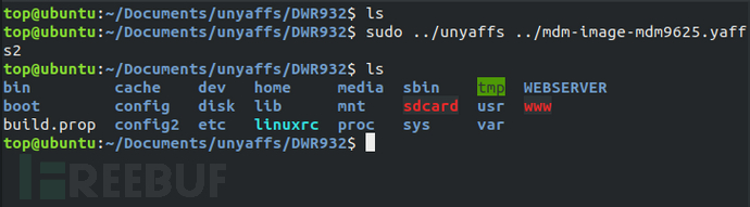
For yaffs filesystem images, you can useunyaffstools to extract its filesystem.
Vxworks Filesystem Extraction
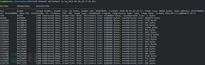
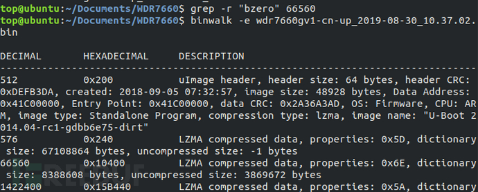
VxWorks is a real-time operating system (RTOS) launched by the US Wind River Systems Company (Wind River Company). The VxWorks system occupies a considerable market share with its excellent real-time performance, including NASA's Mars探测器, Boeing 787 passenger aircraft, network routers, and more, covering various security fields. This test case usesTP-LINKWDR7660 router firmwareUnlike the firmware of the Linux kernel, the Vxworks firmware cannot be parsed by binwalk and needs to be manually analyzed to obtain its filesystem.
Firstly, we used binwalk to analyze the firmware and found a large LZMA compressed file at the address range of 0x10400-0x15B440, which is usually the largest block of the filesystem file. We used dd to read this block of file. Using the command "lzma -d", we decompressed the file and it failed to decompress. We then put the firmware into ghex for analysis.
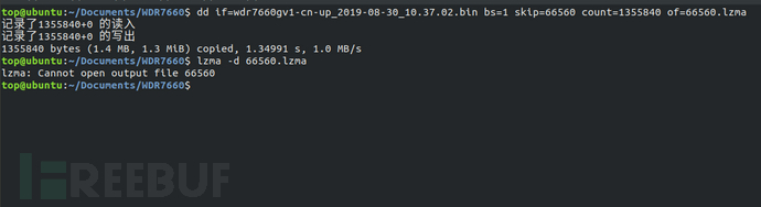
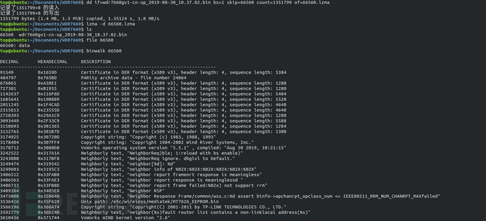
Through ghex analysis, all are FF in hexadecimal before the address 0x15B440, so 0x15B440 is not the end of the LZMA file. By querying the data upwards, we finally found that the end of the LZMA compressed file is at 0x15A477. We then re-extracted the compressed file using dd and decompressed it to obtain the Vxworks filesystem.
In addition to the above filesystem extraction, some firmware may perform various types of encryption, including overall encryption and partial encryption of the firmware, with the purpose of protecting the various modules of the firmware from being easily cracked and extracted. Due to the limited scope of this chapter, in the next chapter, we will introduce the common methods and cases of firmware decryption to the author.
2.2 Filesystem Analysis
After a series of operations from firmware acquisition to the final filesystem extraction, we finally obtained the filesystem of the Internet of Things terminal device. Next, let's analyze the filesystem of the Internet of Things terminal device.
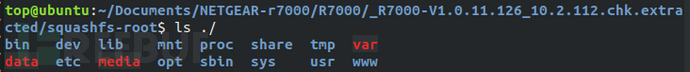
Linux file system directory
Under the root directory of the file system of the test firmware "/", there are many different directories, as shown in the figure below.
Directory | Function |
/bin | The bin(binary) directory stores the basic binary executable files in the system, such as the commonly used "cd", "ls", and others, which are stored in the bin directory. |
/dev | Since the Linux system inherits the characteristics of the Unix system, the Linux system treats all resources as files, even the access ports of external hardware devices are stored in the file system in the form of files, that is, in the /dev(device) directory. Users can access hardware devices by reading and writing these files. |
/lib | /lib(library) directory stores the library files required by the system. |
/mnt | /mnt(mount) directory is used to store manually mounted storage devices or partition directories by users. When a device is recognized by the system, the port to access the device is stored in the form of a file in the /dev directory. If the file system type stored in the device can be identified by Linux, the file system stored in the device can be accessed directly through the /dev directory. However, when the Linux system cannot identify the file system type stored in the device, the user needs to specify the file system format to mount it under the /mnt directory, so that the user can access the file information and content stored in the device. |
/proc | /proc(process) directory is the mount directory of the proc file system. The proc file system is different from the common file system, proc is a virtual file system. The files stored in /proc are a series of special files under the running state of the current Linux kernel, which store information about the system-related hardware and information about the running processes. By changing the content of some of these files, the running state of the kernel can even be changed. The files stored in /proc do not occupy the storage space of ROM, these files are stored in the running memory RAM, so they are also called virtual files. |
/share | /share directory is a shared folder, where users can store files they want to share under the /share directory and share them through local area network or wide area network. |
/tmp | /tmp(temporary) directory stores temporary files. In many read-only file systems, the /tmp directory is one of the few directories mounted to the root directory and can be interacted with by users. |
/var | /var(variable) directory is used to store the directories of data that need to be changed during system operation, such as /var/log(record system log data), /var/lock(record the locking status of system resources), /var/run(record data of logged-in users) and other directories. |
/data | /data directory stores some data files used by the system. |
/etc | /etc (etcetera) directory stores configuration information files of system hardware and software. Such as bash file /etc/rc, /etc/rc.d, /etc/rc*.d executed during system initialization; system user username, password file /etc/passwd, /etc/shadow; firmware version information of IoT terminal devices /etc/version, etc. |
/media | /media directory also stores mounted directories, but unlike the manually mounted /mnt directory, /media directory stores mount points automatically established by the system. |
/opt | /opt (option) directory is used to store additional software packages, and it is a user-level program directory. |
/sbin | /sbin (superuser binary) directory stores binary executable files used by the root user. |
/sys | Similar to the proc file system, sys is also a virtual file system. The sys file system provides users with an entry point to access the kernel space, and by accessing the virtual files under the mount point /sys of the sys file system, users can obtain various kernel information of the system. |
/usr | /usr (Unix Software Resource) directory stores Unix operating system software resources. When the system installs software, it will always use the /usr directory as the default installation directory. The /usr/bin directory usually saves most of the commands used by users; the /usr/include directory stores header files for c/c++ programs; the /usr/lib directory stores dynamic library files of binary executable files in /usr/bin and /usr/sbin; /usr/local stores software installed by system administrators; /usr/sbin stores system instructions required for non-system normal operation, common network server software such as telnetd, dropbear, etc.; /usr/share is consistent with /share, storing shared files. |
/www | /www directory usually stores web page files, web programs, web data, etc. of terminal devices. When analyzing information leakage, unauthorized access, and other vulnerabilities of terminal device web ports, it is important to focus on the /www directory. |
Linux File System Analysis Approach
The following situations may exist security issues in the Linux file system:
Security Risk | Analysis Approach |
Configuration Security Risk | In the file system, common configuration file formats are *.conf, *.cfg, *.ini, etc. |
Information Disclosure | Common sensitive information includes users' accounts and passwords, personal information of users, etc., and common file formats include passwd, shadow, *.psk, etc. |
Key security | Common key or certificate file formats include *.crt, *.pem, *.cer, *.p7b, *.p12, *.key, etc. |
Source code security | Common source code formats include *.c, *.h, *.py, *.lua |
Database security | Common database file formats include *.db, *.sqlite, *.sqlite3, etc. |
Security risks of open-source components | Files with a large number of vulnerabilities in open-source components include busybox, openssl, hostapd |
Security risks of closed-source components | Closed-source components can focus on web components such as apache, lighttpd, mini_httpd, httpd, goahead, boa, as well as upnp components, etc. |
In addition to manually analyzing the above files with high security risks, some commonly used file system analysis tools can also be usedFirmwalkeret al.
- Firmwalker
Firmwalker is an analysis tool written in bash, which covers many string features of sensitive information and dangerous components and can quickly scan the file system and locate files with high security risks in the file system.
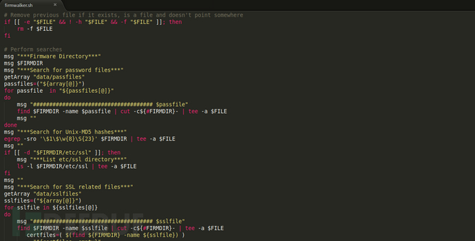
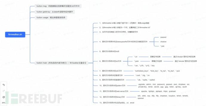
The following diagram is the mind map of the overall bash program of Firmwalker. Firmwalker will store the string features of sensitive information and dangerous components in the database, such as common passfile files, configuration files, key files, database files, source code files, and file names of dangerous components, and match the scanning results with the feature strings during file system scanning.
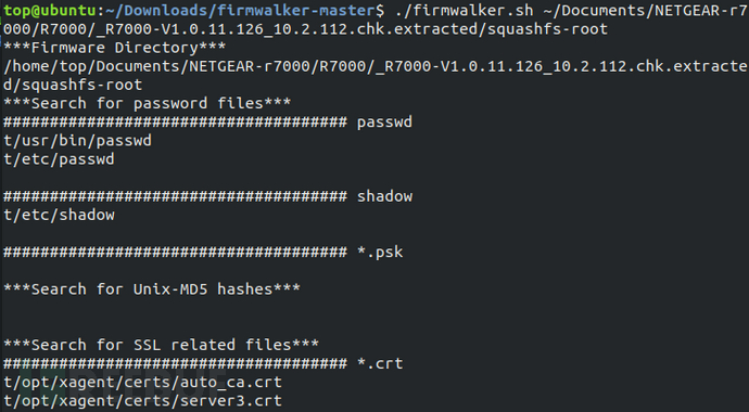
Scan the file system of the test firmware with Firmwalker, and you can see some important sensitive files scanned out.
Vxworks file system analysis
In Section 2.1, we successfully extracted the file system from the WDR7660 firmware, and then continue to analyze the Vxworks file system.
The Vxworks file system is an integral elf file, and it is necessary to analyze its loading address in order to correctly parse the functions in the binary program. To analyze the loading address of the Vxworks file system, disassembly tools are needed, and the mainstream disassembly tools at present areIDAwithghidraet al.
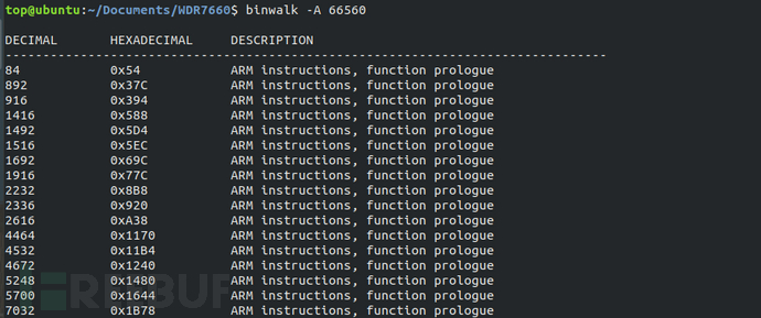
Using the command "binwalk -A xxx" to analyze the file system architecture as ARM, it can be known from the binwalk analysis results in Section 2.1 that the file system is little-endian.
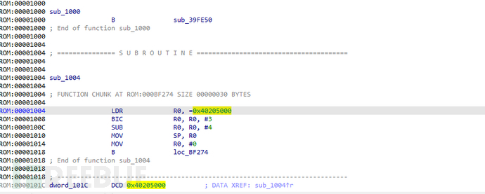
Due to the fact that the loading base address of the VxWorks system is the same as the stack initialization address, according to the official instructions provided by VxWorks, it uses usrInit for stack initialization, and usrInit is the first function to run after the VxWorks system boots. The first appearance of the sp register is the loading base address of the VxWorks system.
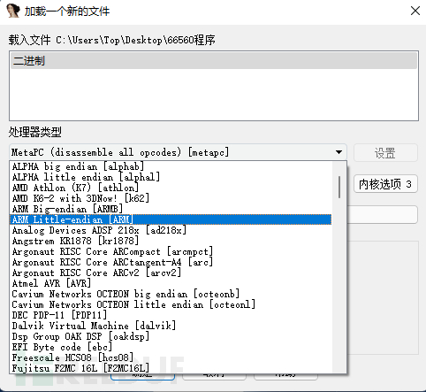
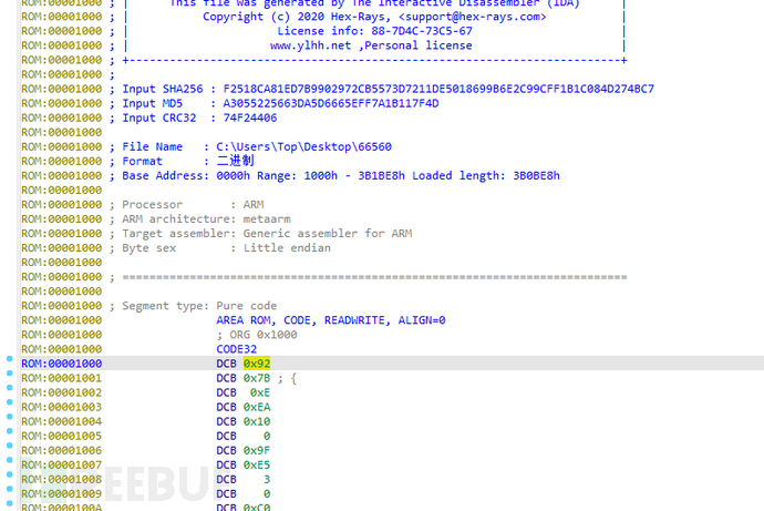
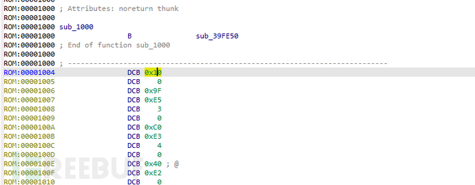
Place the VxWorks system file into IDA, set the processor type to ARM little-endian, set the loading address randomly to 0x1000, and press the 'P' key manually at the first line of DCB assembly after the file is loaded to manually let IDA analyze the assembly.
The first address 0x40205000 appearing on the first SP register is the loading address of the file system.
After determining the loading base address of the Vxworks file system, it is necessary to restore the function name of the file system so that it can be quickly searched for vulnerabilities during subsequent reverse analysis. bzero is a function in VxWorks, which is used to clear the data of the bss area during the system startup process.
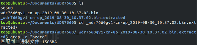
Firstly, use the grep command to search for the bzero character in the elf file of the file system, and find that there is no such string in the elf file, indicating that the symbol table is separated from the file system. Use the 'binwalk -e' command to decompress the WDR7660 firmware, and use the 'grep -r bzero' command to search for the symbol table after decompression, and match the binary file 15CBBA.
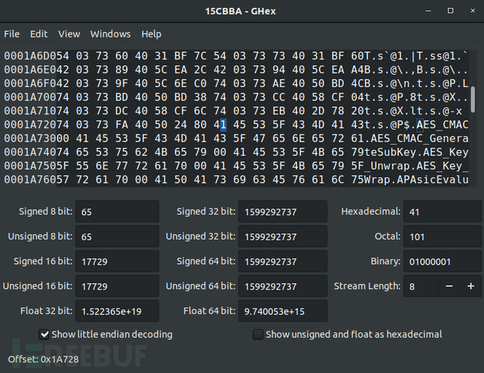
Use the ghex tool to analyze the 15CBBA file, and determine the starting address of the symbol table as 0x1A728.

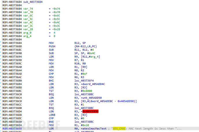
According to the observation, at the address 0x8, there is standardized data in units of 8 bytes. After analysis, the first byte 54 is the flag, the second to fourth bytes are the offset in the symbol table, and the last four bytes are the address of the function corresponding to the symbol in the file system. For example, the address of the first function AES_CMAC in the file system is 0x40373684. Through string information, it can be confirmed that this analysis is correct.

After the symbol table recovery is completed, the subsequent analysis work is based on reverse analysis. We will introduce various methods and skills of reverse analysis to the readers in the following chapters.
The learning of the firmware acquisition method, file system extraction and analysis skills in this issue of 'Play with Internet of Things Firmware' has come to an end. In the next issue, we will continue to introduce to the readersFirmware simulation, firmware packagingMore content is coming soon!
References:
[1] (US) Aaron Guzman, (US) Aditiya Gupta. Internet of Things Penetration Testing. Beijing: Machine Press, May 2019.
[2] http://blog.nsfocus.net/tp-link-wdr/
[3] https://linux.cn/article-9798-1.html
[4] https://elinux.org/File_Systems

评论已关闭